
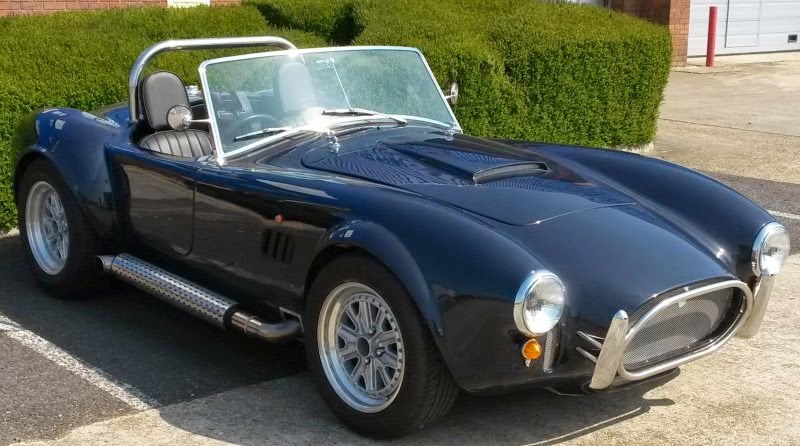
Welcome to my Cobra build diary. I have finished this Pilgrim Sumo Cobra kit car, and this diary will show you the fun and frustration of the build - Started April 2012. Completed car photo (April 2015). I hope you enjoy my build diary.
Saturday 29 December 2012
Column Switches
This diagram has to be the most helpful I've ever seen. This combined with the writing diagram and the Pilgrim manual has made wiring the column switches fairly straight forward. I've only blown 1 fuse when I let a loose wire touch the chassis while testing the indicators.
Fitting the boot
The boot isn't a bad fit, but it isn't perfect. I had to remove the edge all the way around to make it fit. It won't be visible when the boot is shut, and since it is a dark colour I don't think it will be too bad when the boot is open. I have bought some gel coat from Pilgrim to touch up the edge if needed.
I bought the wrong boot seal. It is door seal, i.e. (Side Seal not Top Seal), and the same seal is used for boot and door. The lip around the boot aperture needs to also be trimmed - basically removing the return lip and cutting back so the boot trim sits close to the edge of the aperture. It must be fairly close so the seal doesn't prevent the boot from closing


Next is to fit the two hinges to the top. Very nervous about drilling holes in the body. "Measure twice - cut once"... more like read manual, watch video, think about it, measure, measure, measure again, think about it some more and put off until tomorrow.
Sunday 16 December 2012
Body
The body is now sitting in the garden waiting to be dealt with:
- Attach the boot lid
- Attach the bonnet
- Cut holes for lights
- Start to work on those flash lines!

- Attach the boot lid
- Attach the bonnet
- Cut holes for lights
- Start to work on those flash lines!

Heater
The heater is from a mini, and while it small and fits under the dash is only has one speed and is fairly pathetic. I may change it for a VW Polo heater that has a lot more power, but needs some "modification",
 There is a second photo showing the other side, i.e. the plumbing but it so blurred I have to re-take it!

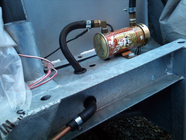
Fuel pump
To start the engine I temporarily connected the fuel pump. Now I have a better understanding of how and where the body fits to the chassis, it is clear the fuel pipe needs to go through the chassis:

Simple...
Simple...
Alternator
Fitting the alternator should have been an easy job. Simply take the Pilgrim Alternator bracket and fit to the Rover V8, then attach the alternator... Sadly, the alternator pulley didn't line up with the water pump and so the bracket needing cutting back to allow the alternator to slide back.
Since the alternator is situated on the other side of the engine then it needs a slight modification. This involved removing the 3 long bolts and rotating the front section - this allows the pivot bolt to sit at the bottom and the 3rd bolt hole to be top-right as shown:


Since the alternator is situated on the other side of the engine then it needs a slight modification. This involved removing the 3 long bolts and rotating the front section - this allows the pivot bolt to sit at the bottom and the 3rd bolt hole to be top-right as shown:

Now the alternator, fans, horn, temperature sender, oil pressure sensor, and coil are fitted the loom can be tidied up and tied down around the front end of the chassis:

Monday 10 December 2012
Cooling fan
Before plumbing the radiator I checked the 2 fans were working and were indeed sucking (or pull) fans, i.e. they pull air from back to front so when mounted on the back of the radiator they will pull the air through. Sadly they were blowing (or push) fans. Switching the polarity made them spin the other way, but due to the way the blades are made they don't work so efficiently in reverse. I returned them to Pilgrim who supplied a single big fan - which when you work out the surface area is bigger than 2 small ones (and cheaper too!).
I made some simple brackets and attached it to the radiator:

My thermostat housing has a bypass outlet to allow water to flow to heater. Trouble is I had no where to connect it as the back of my water pump had only 1 outlet, so I simply put a T piece.
Next is to fill with 50/50 antifreeze and water and check for leaks.

I made some simple brackets and attached it to the radiator:

Plumbing the engine wasn't simple, and the Pilgrim hoses supplied didn't fit the Rover V8, so I returned them and used some flexi hose. For anyone wanting the detail:
- Bottom of Rad connects to bottom of water pump
- Top of Rad connects to front of manifold (where thermostat is housed)
- Back of water pump to connects to heater (via a T piece - see below)
- Heater return connects to the back of manifold
- Expansion tank top and bottom to small pipes on rad top and bottom
My thermostat housing has a bypass outlet to allow water to flow to heater. Trouble is I had no where to connect it as the back of my water pump had only 1 outlet, so I simply put a T piece.
Next is to fill with 50/50 antifreeze and water and check for leaks.

Sunday 28 October 2012
Preparing to "fire it up"
Lots of little jobs (sorry no photos).
- Wired fuel pump
- Connected fuel tank to fuel pump, disconnected it all and added in a fuel filter
- Connected fuel pipe in engine bay to carbs remembering the 2nd fuel filter - not really necessary, but can't hurt and since it is clear plastic you can see the fuel is being pumped to the carbs
- Blanked off the 2nd fuel pipe to the fuel tank (not needed as not using fuel injection)
- Connected the Sierra ignition switch to the loom and tested fuel pump (tick!):
Red - live
Yellow - key position I
Black/Yellow - key position II
Black/Blue - key position III (starting)
- Wired the coil to the DLM8 Distributor (actually to the amplifier/ignition module on the side). No where could I find a circuit diagram for this, but finally figured it out Red to Coil +ve, and Blue to coil -ve.
- Wired coil to ignition switch mkey position II
- Finally wired the oil pressure sensor.
4 things left to do:
- Fill with oil and turn over to ensure the oil pressure light goes out (pump may need priming)
- Bolt on exhausts
- Put some petrol in the tank
- Cross all fingers and pray before turning ignition switch
Monday 22 October 2012
Engine finally in
I finally ran out of those "small" jobs and it was time to fit the engine. After a few attempts, and much swearing I managed to get gearbox to mate with the engine. The clutch was aligned, but the spigot bush was obviously a perfect fit, so the gearbox needed to be perfectly level to slide in. Everything else was prepared and ready to go including, new bushes on the gearbox remote new gearbox mounting rubbers, and new clutch release bearing and arm (just hope it's all correct as I really don't want to EVER separate the gearbox and engine EVER again ;-)

We lowered the engine into the engine bay with no trouble at all (thanks Michael), until it became obvious that the engine mounts would not fit. After much measuring and more swearing I realised (OK Michael did), that I had the engine mounts the wrong way around - whoops!


The Loom
The hardest part about the loom is working out which wire is which. From experience I have learnt that labelling every wire saves so much time later on. So in front of the fire I laid out the loom front to back and labelled each wire. I also spotted a few mistakes in the wiring diagram and Pilgrim had supplied the wrong type of relay (Type A and Type B are not the same pin-out).
The next tricky bit is feeding all the wires through a hole in the bulkhead (not forgetting the rubber grommet - thanks ebay!). After that the fuse and relay holders need securing to the side (and top in my case) of the drivers side footwell:

The rest of the loom has been "laid" onto the chassis and temporarily cable tied in roughly the right place.
Sadly the Pilgrim loom is generic, so a number of the engine bay wires need to be shorten, e.g. the RoverV8 starter is drivers side. Not a difficult job, but a shame to un-bind the loom to remove wires.
The next tricky bit is feeding all the wires through a hole in the bulkhead (not forgetting the rubber grommet - thanks ebay!). After that the fuse and relay holders need securing to the side (and top in my case) of the drivers side footwell:

Sadly the Pilgrim loom is generic, so a number of the engine bay wires need to be shorten, e.g. the RoverV8 starter is drivers side. Not a difficult job, but a shame to un-bind the loom to remove wires.
Hydraulic Clutch
As previously posted the Sumo is design to work with a cable operated clutch as this connects to the Sierra pedal box. Problem is that the clutch is designed for hydraulic which makes a cables operated clutch stiff and unreliable. So the pedal box has been modified and fitted with a clutch cylinder. Here you see the pedal box and master cylinder under the dash
 And here's the fluid reservoir and the fluid line down the bulkhead to the slave cylinder
 All quite straightforward to fit - thanks Tony for supplying the mod and parts
I now need to bleed the whole system as nothing happens when I press the clutch pedal - really hope it's an airlock...;-)


I now need to bleed the whole system as nothing happens when I press the clutch pedal - really hope it's an airlock...;-)
Monday 13 August 2012
Flywheel, Clutch and Gearbox
Life is always simple when the gearbox and engine come from the same car - in my case they didn't and that's where the fun started. I have a Rover V8 3.9l (and 3.5l) from Land Rover Discovery. There are 4WD cars, with gearboxes unsuitable for the Cobra. So I sourced an LT77 2WD box. Once I had figured out I needed a 2WD bellhousing, I thought I was ready to roll.
I bought a new clutch plate and cover to match the engine - WRONG! The 4WD Clutch cover is too large for the 2WD bellhousing, so off I went in search of a 2WD clutch plate/cover - which fits a Rover SD1. Guess what, it didn't fit onto the 4WD flywheel. At this point I wanted to cry and wonder how far back I was going to have to go to make it all fit. Someone from the cobra forum came to my rescue and sold me a spare SD1 flywheel, clutch plate/cover, and release bearing - Perfect! Rimmer Bros supplied the clutch release arm and it all looks good:

The new one is simply fitted by putting in the freezer over night to make it as small as possible, covering with grease and tapping into place.

I bought a new clutch plate and cover to match the engine - WRONG! The 4WD Clutch cover is too large for the 2WD bellhousing, so off I went in search of a 2WD clutch plate/cover - which fits a Rover SD1. Guess what, it didn't fit onto the 4WD flywheel. At this point I wanted to cry and wonder how far back I was going to have to go to make it all fit. Someone from the cobra forum came to my rescue and sold me a spare SD1 flywheel, clutch plate/cover, and release bearing - Perfect! Rimmer Bros supplied the clutch release arm and it all looks good:

A trial fit of it all showed that the spigot bush was too large for the 2WD bearbox shaft. The spigot bush shown below fits into the centre of the crank shaft exposed through the flywheel (shown above). The one fitted is intended for the 4WD shaft, and is a few mm bigger. Without the correct spigot bush the end of the gearbox shaft would not be correctly supported. Question is how does one remove the old one? Advise from the forums and a YouTube video shows a simple solution. It is counter intuitive to hammer something in to make it come out - I understood the idea behind it, but was sure that I would just end up covered in grease - But it worked ;-)
The new one is simply fitted by putting in the freezer over night to make it as small as possible, covering with grease and tapping into place.

Pilgrim recommend using a clutch cable, but having heard that this gives a stiff clutch pedal and even stories of snapped cables, I have decided to get a forum-buddy to make me a Hydraulic Clutch conversion - watch this space... In the meantime, it's loom time!
Off with the head
While stripping the engine I discovered that the previous owner had snapped an exhaust stud - v.frustrating. In the past I have never had much luck with removing snapped studs using various methods and tools, so I decided to let a professional do it. A machine shop were able to machine the stud out for a few quid. It did mean removing the head though


All now re-built with new gasket, and new head bolts. The Edelbrock inlet manifold, carbs, and rocker covers have been transferred from the 3.5l to the 3.9l.
Radiator Fitted
This is one of the simpler jobs. The hardest part is cutting parts off the brand new out of the box rad. As you can see from the image below, the bottom brackets need to be trimmed, and the plastic side supports cut off.

Once done, the rad is fitted to the front of the chassis with some home made brackets and M8 bobbins (bought from Ebay). The brackets still need to be trimmed once I fit the body depending how far back/forward the rad needs to sit.


Monday 28 May 2012
Engine Shuffle
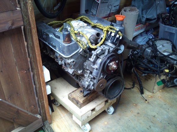
To cut a long story short the 3.5ltr Rover v8 engine I bought turned out to be a 1993 engine and not 1992. This means that it is subject to more stringent emissions tests which would probably mean a Cat. So I bought a 1990 3.9ltr Rover v8 (more BHP than the 3.5!)
I need to keep the 3.5ltr and in order to make space I put the 3.5ltr in the shed and the 3.9ltr next to the chassis ready to go into the car. Getting a engine into a shed proved a little challenging, but with the aid of a dolly trolley that I made I succeeded:

I need to keep the 3.5ltr and in order to make space I put the 3.5ltr in the shed and the 3.9ltr next to the chassis ready to go into the car. Getting a engine into a shed proved a little challenging, but with the aid of a dolly trolley that I made I succeeded:
Sunday 27 May 2012
Steering rack and column
The Steering rack and column went in over the weekend. Took much longer than I anticipated. When I set the wheel alignment to 0 deg I found that the track rod ends need to be wound all the way in. Sadly the threads on the track rods were rusted from never being used on the old Sierra donor, and with little to hold onto it was impossible to simple wind the nut on. It took me a while to wire brush both sides and finally get the nuts and track rod ends to their correct position.
The steering column goes through a hole in the bulkhead that is way too big for the Sierra column bush, so with advice from the forums I bought a £10 bearing to fit in the hole. The guys at BearingBoys did a great job in sending it the next day:


 The steering column needs extending which was a simple task if you follow the method in the manual. Once extended it no longer rubbed on the brake pedal which was an initial worry (instant IVA failure!).
The steering column goes through a hole in the bulkhead that is way too big for the Sierra column bush, so with advice from the forums I bought a £10 bearing to fit in the hole. The guys at BearingBoys did a great job in sending it the next day:
And here it is fitted to the bulkhead:


Tuesday 22 May 2012
On all fours...
Here's the missing picture of the diff in place. It wasn't quite as hard as I had imagined to lift and bolt in:


The handbrake is in place and attached but needs some serious tightening up which I'm sure is possible...I hope. Now that the all the brakes and suspension is in place I could resist bolting on the wheels and letting it sit on all four for the first time!

Sunday 13 May 2012
Rear Brake Lines
Much the same as the front brakes. Lots of measuring, flaring, drilling, and riveting, taking great care to ensure there are enough clips holding the brake pipe to keep Mr.IVAman happy. There is no specified distance in the IVA manual, but they mustn't move AT ALL. More clips is safer and also ensuring that the pipe doesn't touch the chassis as it bends around corners.
The pipe runs along the drivers side from the master cylinder and under the rear end where it splits via a t-piece shown below.

Up and over the tunnel (glad I didn't fit the diff first! ) to the other flexi-hose:

This last photo also shows the handbrake cable in place and attached to the handbrake poking through the tunnel.
The diff (picture to follow) was tricky to get in. I eventually managed it by raising it on a trolley jack, fitting the bracket as I lifted it and the lower the chassis to get it into it's final position. Did it 1 handed too!
Thursday 10 May 2012
Front brake lines
Fairly simple job once I remembered how to flare a brake line - it's been a while!
Pictures of both side:


Next the rear brakes. This is a long run down the side of the body to the back where it splits via a T-piece to each of the rear brake drums. Then the plan goes something like this, Diff, Drive shafts, rear brake assembly, Wheels, Engine, Christmas ;-)
Pictures of both side:


Next the rear brakes. This is a long run down the side of the body to the back where it splits via a T-piece to each of the rear brake drums. Then the plan goes something like this, Diff, Drive shafts, rear brake assembly, Wheels, Engine, Christmas ;-)
Sunday 6 May 2012
Not quite rolling
As with all kit cars, plans often go out the window. It is the beginning of May and my plan for a rolling chassis by end-April was a little ambitious... Mainly due to lack of time, other things going wrong, and some extra DIY on my car port ;-)
Putting the rubber/steel bushes into the suspension parts proved a lot harder than I thought. Hitting with a hammer clearly wasn't going to work and winding in with a vice didn't quite cut it either. I asked the local garage to use their hydraulic press to push them in which they did for a few quid.
Front suspension went in without any major problems as the manual is quite helpful here
 The other side looks the same ;-)
I did fit one side of the rear suspension and started to trial fit the diff - this is clearly a 2 man job as one person needs to raise the diff on a jack while the other fits the bolts. While checking the position and making sure the bolts fit, I realised that fitting the brake pipes after the diff would be a real pain, so I abandoned the rear end and started on the brakes (manual is less helpful here!)
Here you can see the brake servo and master cylinder from the sierra donor. This bolts on to the bulkhead and connects to the pedal box (next picture below). This is a simple (not) matter of doing up 2 nuts as the 2 parts fit together. a) the hole for the clutch cable wasn't big enough and b)it is another 2 man job (thanks Alex), as one person needs to hold the servo, while the other does up the nuts in drivers footwell.
 Clutch and brake pedal. Alex and I sat in the car and pressed the pedals....;-) Exciting!

I got bored of getting wet, and getting rid of pools of water from the tarpaulin covering the chassis. So I adding some posts and clear plastic roofing sheets to keep everything dry. Another 2 man job - thanks Michael for all your help!
 Next week brake pipes if I can find the right size rivets...
Putting the rubber/steel bushes into the suspension parts proved a lot harder than I thought. Hitting with a hammer clearly wasn't going to work and winding in with a vice didn't quite cut it either. I asked the local garage to use their hydraulic press to push them in which they did for a few quid.
Front suspension went in without any major problems as the manual is quite helpful here

I did fit one side of the rear suspension and started to trial fit the diff - this is clearly a 2 man job as one person needs to raise the diff on a jack while the other fits the bolts. While checking the position and making sure the bolts fit, I realised that fitting the brake pipes after the diff would be a real pain, so I abandoned the rear end and started on the brakes (manual is less helpful here!)
Here you can see the brake servo and master cylinder from the sierra donor. This bolts on to the bulkhead and connects to the pedal box (next picture below). This is a simple (not) matter of doing up 2 nuts as the 2 parts fit together. a) the hole for the clutch cable wasn't big enough and b)it is another 2 man job (thanks Alex), as one person needs to hold the servo, while the other does up the nuts in drivers footwell.


I got bored of getting wet, and getting rid of pools of water from the tarpaulin covering the chassis. So I adding some posts and clear plastic roofing sheets to keep everything dry. Another 2 man job - thanks Michael for all your help!

Wednesday 4 April 2012
Today I picked up the chassis and all the parts needed to build a rolling chassis. My goal is to get it on it's wheels before the end of April. The 1 week business trip away will probably put a spanner in that idea, but we can dream:
- Prime and paint all suspension components
- Seal cockpit area of chassis against water
- Drill all holes to remove excess zinc coating from the Galvanising process
- Front suspension arms
- rear suspension arms
- Wheels!

Thursday 15 March 2012
It's on order!
The kit has been ordered....well enough parts to build the rolling chassis!
Slow week and I've lost my wheel nuts from the original Sierra donor - another thing lost in the move.
I've starting cleaning up the re-painting the old rusty sierra parts - from rusty to shiny:

Assembled a Chicken shed for my wife instead of working on the rusty parts today ;-)
Slow week and I've lost my wheel nuts from the original Sierra donor - another thing lost in the move.
I've starting cleaning up the re-painting the old rusty sierra parts - from rusty to shiny:

Assembled a Chicken shed for my wife instead of working on the rusty parts today ;-)
Thursday 8 March 2012
Small jobs
I cleaned the starter motor and fitted it and the flywheel - simple!
For fun (!) I dug out the ignition key and switch; wired up the starter and turned the engine over. Nothing went bang which was a good sign. Debating whether to add some fuel and a spark (or 8) and fire it up, but without any exhaust it will just be painful. Good to know the battery still works.
LT77 Gearbox bellhousings are proving to be a pain. The one I was sold with the gearbox turned out to be for a 4WD gearbox so I'm returning that. Saw one last night on ebay, but turned out not fit a v8 (starter and clutch holes need to be on the same side - this one might have fit, but the clutch cable would have been at the top...;-( So Beware when buying LT77s and Bellhousing.
Now, I'm running out of jobs to do, and it's time to BUY THE KIT....!!
Monday 5 March 2012
It's never simple!
The inlet manifold is cooled by water flowing through it and it houses a thermostat to allow coolant to only flow around the engine when the engine reaches a certain temperature. However, the old Rover V8 EFi inlet manifold thermostat housing doesn't fit the Edelbrock inlet manifold, as there is a thermo by-pass outlet (not sure why...). So I needed to get a different (new) thermo housing, which was £45 I hadn't budgeted for. I found one on Ebay for 1/2 that amount.....BUT the pipe is slightly longer (I realised when it arrived) and it touches the vacuum advance on the distributor. Easily solved by moving the distributor round one notch and re-timing. I decided to move it a full 180deg to make more room - time will tell if this was a wise move:


I also swapped over the water temp sensor from the old manifold and found the PCV valve too. The latter is a one way valve that allows air to be drawn into the manifold, but not out - it is used to create a vacuum for the brake servo.
Next job - re-fit the water pump with new gasket. A nice simple job, clean the bolt threads, fail to find the missing bolt, order new one from ebay, apply sealant to gasket, fit water pump and tighten bolts to specified torque - simple. The last bolt, on the last turn when CRACK, and cracked the casing. See below. I guess torque wrenches are not that accurate and the casing was weak at that point. Not worth risking the leak so another £39 on Ebay for a replacement pump.

Summary: an expensive and frustrating week.... Ah, but that's what kit cars are all about - ups and downs, achievements and sorrows, and all have their cost.
Next job on the list is to re-fit the Flywheel, Clutch, and starter.
Thursday 23 February 2012
New Shiny Bits
The new 'Shiny' bits have arrived...(I love ebay!):
JRV8 in Ireland is a star, sent me 2 clamps the very next day!
Here are the pictures of the New Shiny bits:
Inlet Manifold:
 Rocker Covers:
 Edelbrock Carburetor:
 (thanks to you know who!!)
And finally the Air filter:
(thanks to you know who!!)
And finally the Air filter:

- New Edelbrock carbs
- New inlet manifold
- New rocker covers
- New air filter
JRV8 in Ireland is a star, sent me 2 clamps the very next day!
Here are the pictures of the New Shiny bits:
Inlet Manifold:


 (thanks to you know who!!)
The Beginning...
The beginning actually happened several years ago when I sold my previous kit car (Tiger Cat) to make way for a new build. At the time, life became busy and rather than invest in the kit I bought a Rover v8 from Ebay and spend some time stripping, cleaning and reconditioning it. Life is now slightly less busy, and time has come to move the project on one more step.

The house move (a whole other story) has left me without a garage, but there is a car port and a huge shed (not this one ;-). The car port isn't ideal, but with a few modification I can work on the car in most weathers. With power in the "huge" shed I effectively have power in the car port for lighting, drilling, and cutting, etc.
I have built a 2nd shed (shown left) and the push bikes are now tucked away leaving the car port clear... well nearly.

Step 2: Finish engine rebuild, add carbs and get it started.
Subscribe to:
Posts (Atom)