After 4 weeks I finally received a letter from the DVLA. Thinking that this must be the letter I had been waiting for I quickly ripped open the envelope only to find bad news.... They were requesting that I:
a) Re-stamp the chassis and VIN Plate with a NEW VIN number issued by them. Not sure why, but arguing didn't help
b) Inform HMRC of the new VIN number (which they issued...!) via their NOVA system. NOVA stands for Notification of Vehicle Arrival, and is used to inform HMRC of cars coming to the UK from other countries! WHAT! I argued (politely), but they insisted this was the new process.
2 weeks later and a few nudging via again polite phone calls, I received my v5 document. PHEW!
The sun is shining and I have number plates and a big smile on my face!!
My advice to other builders would be to check with DVLA before you stamp the VIN number on your chassis and check whether a NOVA application is required. Get the NOVA application started at the same time as your DVLA application - it'll save 2 weeks.

Welcome to my Cobra build diary. I have finished this Pilgrim Sumo Cobra kit car, and this diary will show you the fun and frustration of the build - Started April 2012. Completed car photo (April 2015). I hope you enjoy my build diary.
Saturday, 23 May 2015

Friday, 10 April 2015
It is finished (well nearly...)
The IVA re-test was a success and I have received my IAC certificate - a truly wonderful feeling that after 3 years of fun, and frustration I have finally finished the Cobra. Well nearly, because we all know that a kit car is never really finished.
Fixing the two problems were simple, once I figured out the how.
No.1 Indicators at the wrong height:
I made some small brackets and mounted the indicators up by 3cm. I was going to try jacking up the suspension again, but 3cm seemed a lot and making the bracket was a simple job and I didn't need to change the wiring.

No.2 No Self Centring:
The failure was more on the fact that at 3/4 lock the steering pulled to full lock (so opposite to self centring), which he rightly considered to be dangerous. I had to limit the lock to lock steering by adding steering limiters to the rack. This was easy; the hard part was making the car self centre. Lots of help from the forums and the advice was to increase the caster angle, but sadly that made no difference - I believe I had enough caster angle and increasing it didn't help. I checked and adjusted the camber angle, but still no self centring. I pumped the tyres up, but still nothing. And I knew that even though I had solved the anti-self centring, I need to show some degree of self centring for Mr. IVA.
I started to go down the route of wheel offset as the -21mm ER I had on my new wheels was quite different to the -38mm offset on the original Sierra wheels. Before I went too far down that route, I found that the one thing I thought I'd got roughly right was the Toe-in, but I discovered that my method of measurement was woeful! Armed with a laser, I re-measured the Toe in and discovered it was incorrect and needed 3 turns on the tie-rods to correct it to 0 degrees. A little more tyre pressure and I had self centring! Yes!
The re-test took 10 mins and cost me £90 - ouch.
I've now filled in all DVLA forms and posted it all off to our friends in Swansea - hoping for a swift (3 weeks) return before the sunshine disappears.
Fixing the two problems were simple, once I figured out the how.
No.1 Indicators at the wrong height:
I made some small brackets and mounted the indicators up by 3cm. I was going to try jacking up the suspension again, but 3cm seemed a lot and making the bracket was a simple job and I didn't need to change the wiring.
The failure was more on the fact that at 3/4 lock the steering pulled to full lock (so opposite to self centring), which he rightly considered to be dangerous. I had to limit the lock to lock steering by adding steering limiters to the rack. This was easy; the hard part was making the car self centre. Lots of help from the forums and the advice was to increase the caster angle, but sadly that made no difference - I believe I had enough caster angle and increasing it didn't help. I checked and adjusted the camber angle, but still no self centring. I pumped the tyres up, but still nothing. And I knew that even though I had solved the anti-self centring, I need to show some degree of self centring for Mr. IVA.
I started to go down the route of wheel offset as the -21mm ER I had on my new wheels was quite different to the -38mm offset on the original Sierra wheels. Before I went too far down that route, I found that the one thing I thought I'd got roughly right was the Toe-in, but I discovered that my method of measurement was woeful! Armed with a laser, I re-measured the Toe in and discovered it was incorrect and needed 3 turns on the tie-rods to correct it to 0 degrees. A little more tyre pressure and I had self centring! Yes!
The re-test took 10 mins and cost me £90 - ouch.
I've now filled in all DVLA forms and posted it all off to our friends in Swansea - hoping for a swift (3 weeks) return before the sunshine disappears.
Sunday, 29 March 2015
IVA Test
IVA Test March 2015 at Southampton
I spent the day before going over the car, tightening bolts, checking the lights/electrics and checking all the projections. I didn't sleep well the night before and was extremely nervous.
In summary it was a good day, but a very stressful drive to the test centre as it was only the 2nd time I had driven it and I was worried it would breakdown even before I got to the test :-)
It passed on everything expect:
- Front indicators were too low - they should beat least 350mm from the ground to the BOTTOM of the lens. I measured mine from the middle of the lens
- No self-centring
Hopefully the detail below will give you an idea of what happens on the day; this is the order of tests at my IVA:
Under-car inspection
8am and I drove straight onto the car lift and sat there performing various tasks like turning the wheel, pressing the brake and pulling the handbrake. He checked all the wiring, brake/fuel pipes, etc. from underneath. He also checked the VIN number on the chassis and VIN plate. He checked the engine number and prove of engine age.
Lights
Next all the lights were tested, including the fog light which confuses a lot of people. Basically the fog light must not be on, when the lights are off or on side lights. It can only come on when the lights are dipped or full beam - this in the Pilgrim is achieved by a separate relay for the fog lights which is
powered by dipped lights. So no dipped lights, no fog lights!
Thankfully he let me adjust the headlights as while they passed the MOT, I had jacked up the suspension to ensure the front indicators were above 350mm from the grouns.
Failure No. 1: The indicators were less than 350mm from ground to BOTTOM of lens. I had been measuring them from the middle of the lens.
Wheel nut removal
He asked me to remove one wheel nut from the front and back wheels as the nuts were enclosed.
Interior
He looked in boot, but since it was all carpeted, nothing to see there. He had a good wiggle of steering column, thankfully I had re-enforced it with a steel plate.
Seat belts. He spend a long time on these which is a good thing. I showed him pictures of how it was constructed, including the mod I made (see earlier post) and the Pilgrim EU approval. I don't know if he had reviewed it on their database as I had mentioned it in my IVA application, but my explanation and pictured satisfied him. He spent lots of time spent measuring seat belt position, headrest and shoulder height. He then had to get a spy-style camera on a stalk to feed behind the seat to see the seat belt bolts
Mirrors
Next I drove onto the grid for the mirror check where he aligned various red and green magnets on the wall behind him. All fine, phew
Outside in the car park
Then outside for a skid test - this I wasn't expecting as it wasn't part of my SVA for my 1st kit car. Basically in the car park I had to drive up to 20mph and do an emergency stop next to him. He was checking the front locked up before the rear and I guess other things too. I quite enjoyed that test!
Then the exhaust sound test which I was really worried about as I had no way to know what it was
going to be. I had put 4500 rpm for max power for my v8 which meant I was measured at 3750rpm, and it came up at 95dB. 99dB being the pass line. He said he was surprised as he said he could hear me arriving 5 minutes before I arrived :-)
Next he drove it around the car park to check general steering and self centring.
Failure No. 2: On 3/4 lock the car turned into full lock rather than self centring which he considered to be dangerous - which I guess it is if you are not expecting it. There was no self centring evident.
Speed test on rollers
I was confident this would pass as I had calibrated the speedo with my Sat Nav on the way to the MOT and knew it was reading nicely over the "real" speed.
Emissions
Again, I knew this would pass as it had already pass the MOT. Key point with this was prove of engine age. The first engine I bought of ebay turned out to be a 1992 engine and would have needed a CAT, so I made sure next one I bought was 1991.
Brake test on rollers
This was a little worrying as it is quite a long test. He had to measure front and back brakes at 5 different rates, and then again with the engine off, i.e. without the servo assist. While I watched he kept pulling strange faces and tutting. In the end I realised he was getting frustrated with the rollers and the infra red controls, and there was nothing wrong with my brakes. He then took all the calculations and said he was going to feed them in to the computer and he would be back shortly. I just sat there staring into space and trying not to hold my breath :-) It passed the brake test!
Projections
Next was projections test where he wandered around the car with the 100mm ball to see if all the projections had the right radius. Again I was prepared for this one and was confident it would pass. This part of the test also included the check of wheels being outside the plan of the car. The test of my first kit car (back in the SVA days) failed on this by 1mm! Thankfully they have a proper tool/template which they hold up against the side of the car to ensure the wheels (not tyres) are not outside the plan of the car. Thankfully the Pilgrim with Image Halibrands doesn't have any problems here.
Overall a good day and he was very friendly and fair. I'm kicking myself for not spotting the self
centring issue, but it is a difficult one to test as you need to be doing over 10 mph. I should have
tested it on the way to the MOT, but had so many other things on my mind - speedo cailbration been the main one.
2 failures now fixed and IVA re-test of the 2 failures is now booked and I'm confident it will pass.
I spent the day before going over the car, tightening bolts, checking the lights/electrics and checking all the projections. I didn't sleep well the night before and was extremely nervous.
In summary it was a good day, but a very stressful drive to the test centre as it was only the 2nd time I had driven it and I was worried it would breakdown even before I got to the test :-)
It passed on everything expect:
- Front indicators were too low - they should beat least 350mm from the ground to the BOTTOM of the lens. I measured mine from the middle of the lens
- No self-centring
Hopefully the detail below will give you an idea of what happens on the day; this is the order of tests at my IVA:
Under-car inspection
8am and I drove straight onto the car lift and sat there performing various tasks like turning the wheel, pressing the brake and pulling the handbrake. He checked all the wiring, brake/fuel pipes, etc. from underneath. He also checked the VIN number on the chassis and VIN plate. He checked the engine number and prove of engine age.
Lights
Next all the lights were tested, including the fog light which confuses a lot of people. Basically the fog light must not be on, when the lights are off or on side lights. It can only come on when the lights are dipped or full beam - this in the Pilgrim is achieved by a separate relay for the fog lights which is
powered by dipped lights. So no dipped lights, no fog lights!
Thankfully he let me adjust the headlights as while they passed the MOT, I had jacked up the suspension to ensure the front indicators were above 350mm from the grouns.
Failure No. 1: The indicators were less than 350mm from ground to BOTTOM of lens. I had been measuring them from the middle of the lens.
Wheel nut removal
He asked me to remove one wheel nut from the front and back wheels as the nuts were enclosed.
Interior
He looked in boot, but since it was all carpeted, nothing to see there. He had a good wiggle of steering column, thankfully I had re-enforced it with a steel plate.
Seat belts. He spend a long time on these which is a good thing. I showed him pictures of how it was constructed, including the mod I made (see earlier post) and the Pilgrim EU approval. I don't know if he had reviewed it on their database as I had mentioned it in my IVA application, but my explanation and pictured satisfied him. He spent lots of time spent measuring seat belt position, headrest and shoulder height. He then had to get a spy-style camera on a stalk to feed behind the seat to see the seat belt bolts
Mirrors
Next I drove onto the grid for the mirror check where he aligned various red and green magnets on the wall behind him. All fine, phew
Outside in the car park
Then outside for a skid test - this I wasn't expecting as it wasn't part of my SVA for my 1st kit car. Basically in the car park I had to drive up to 20mph and do an emergency stop next to him. He was checking the front locked up before the rear and I guess other things too. I quite enjoyed that test!
Then the exhaust sound test which I was really worried about as I had no way to know what it was
going to be. I had put 4500 rpm for max power for my v8 which meant I was measured at 3750rpm, and it came up at 95dB. 99dB being the pass line. He said he was surprised as he said he could hear me arriving 5 minutes before I arrived :-)
Next he drove it around the car park to check general steering and self centring.
Failure No. 2: On 3/4 lock the car turned into full lock rather than self centring which he considered to be dangerous - which I guess it is if you are not expecting it. There was no self centring evident.
Speed test on rollers
I was confident this would pass as I had calibrated the speedo with my Sat Nav on the way to the MOT and knew it was reading nicely over the "real" speed.
Emissions
Again, I knew this would pass as it had already pass the MOT. Key point with this was prove of engine age. The first engine I bought of ebay turned out to be a 1992 engine and would have needed a CAT, so I made sure next one I bought was 1991.
Brake test on rollers
This was a little worrying as it is quite a long test. He had to measure front and back brakes at 5 different rates, and then again with the engine off, i.e. without the servo assist. While I watched he kept pulling strange faces and tutting. In the end I realised he was getting frustrated with the rollers and the infra red controls, and there was nothing wrong with my brakes. He then took all the calculations and said he was going to feed them in to the computer and he would be back shortly. I just sat there staring into space and trying not to hold my breath :-) It passed the brake test!
Projections
Next was projections test where he wandered around the car with the 100mm ball to see if all the projections had the right radius. Again I was prepared for this one and was confident it would pass. This part of the test also included the check of wheels being outside the plan of the car. The test of my first kit car (back in the SVA days) failed on this by 1mm! Thankfully they have a proper tool/template which they hold up against the side of the car to ensure the wheels (not tyres) are not outside the plan of the car. Thankfully the Pilgrim with Image Halibrands doesn't have any problems here.
Overall a good day and he was very friendly and fair. I'm kicking myself for not spotting the self
centring issue, but it is a difficult one to test as you need to be doing over 10 mph. I should have
tested it on the way to the MOT, but had so many other things on my mind - speedo cailbration been the main one.
2 failures now fixed and IVA re-test of the 2 failures is now booked and I'm confident it will pass.
Gaiters, Seats and Carpet
Thankfully I remembered to fit the tunnel carpet before I fit the dash and had even planned it into the fitting of the heater. Once the dash was in, I cut down the gearstick to a level where it didn't feel like I was driving a truck, and it didn't touch the dash in 1st, 3rd, or 5th. The gaiters were easy to fit and looked good with the chrome surround:

The interior side panels needed a fair amount of trimming to fit snugly against the rubber door seal. I decided to fit them so they could be removed to give me access to the door mountings. Except that they needed to be sealed at the rear to prevent any road grime into the cockpit. So I fibre glassed the rear end of them as shown and cut them in half so the front section could be removed. Once the carpet was laid on top it nicely hid all this.

Getting the seats in was easy, but I struggled to get the bolts lined up with holes I drilled. They look great and been able to sit in the car and make brmm brmm noises was a good day!

The interior side panels needed a fair amount of trimming to fit snugly against the rubber door seal. I decided to fit them so they could be removed to give me access to the door mountings. Except that they needed to be sealed at the rear to prevent any road grime into the cockpit. So I fibre glassed the rear end of them as shown and cut them in half so the front section could be removed. Once the carpet was laid on top it nicely hid all this.
Getting the seats in was easy, but I struggled to get the bolts lined up with holes I drilled. They look great and been able to sit in the car and make brmm brmm noises was a good day!
Inside the boot
This part of the build seemed to take forever for something that doesn't appear that complex. In summary it involved:
- Trimming and fitting the rear inner arches
- Board off the fuel tank
- Fitting the carpet
However, it wasn't that simple. Fitting the inner arches involves many trial fittings and trimming of the fibre glass and then securing them in so they seal in the boot and behind the seat. Learning to fibre glass was a new skill and is actually quite simple once you have the right kit ( thanks ebay!) I decided that unlike the front wheel arch inners these didn't need to be removable:

I decided to board in the fuel tank away from the boot itself. I wasn't sure if it was an IVA requirement, but the less Mr. IVA can see the better and I felt it was neater to have one flat edge to fit the carpet to. It proved a good decision as during the IVA he opened the boot and took one look and closed the lid saying there wasn't much to see in there :-)
The board is made of 2 pieces of marine ply attached to the bottom and sides of the boot allowing the number plate light wire to appear and up to the boot.

I've lost count of the number of times I have had to remove those panels:
- After fitting, the fuel pump failed and had to be replaced.
- After replacing the fuel pump a fuel smell developed in the boot (not good!)
- After re-fitting and tighening all unions the smell was still there
- Finally narrowed it down the plastic fuel filter - frustrating as it was only slightly porous, so needed to be felt over night before any smell became evident.
- Trimming and fitting the rear inner arches
- Board off the fuel tank
- Fitting the carpet
However, it wasn't that simple. Fitting the inner arches involves many trial fittings and trimming of the fibre glass and then securing them in so they seal in the boot and behind the seat. Learning to fibre glass was a new skill and is actually quite simple once you have the right kit ( thanks ebay!) I decided that unlike the front wheel arch inners these didn't need to be removable:
The board is made of 2 pieces of marine ply attached to the bottom and sides of the boot allowing the number plate light wire to appear and up to the boot.
I've lost count of the number of times I have had to remove those panels:
- After fitting, the fuel pump failed and had to be replaced.
- After replacing the fuel pump a fuel smell developed in the boot (not good!)
- After re-fitting and tighening all unions the smell was still there
- Finally narrowed it down the plastic fuel filter - frustrating as it was only slightly porous, so needed to be felt over night before any smell became evident.
Grills
The grills on the front (4 in total) can be purchased from Pilgrim, but I found it cheaper to purchase the mesh and cut my own from B&Q. Also you can choose the size of mess to allow more air flow into the radiator. I fixed the bottom grill with tiger sealant as it won't ever need to come out again. The middle and 2 side grills were fit with small flathead M4 nuts and bolts so they can be removed. While building I frequently needed access through all 3 of the whole, so good to make the removable.

Door cards
Like the dash I went for simple door cards without the extra pocket. I didn't like the look of the extra pocket on the front and if I find limited storage a problem I can always add them later.
Fitting the vinyl was a lot simpler as stapling was quicker that the glue gun. As you can see the fir tree panel clips have already been fitted with matching holes on the inside of the doors. These are nicely invisible and strong once the door cards are fitted. Thankfully they are not so strong as to be permanent - I recently had to remove a door card and while hard they do pop out.

Job done!

Fitting the vinyl was a lot simpler as stapling was quicker that the glue gun. As you can see the fir tree panel clips have already been fitted with matching holes on the inside of the doors. These are nicely invisible and strong once the door cards are fitted. Thankfully they are not so strong as to be permanent - I recently had to remove a door card and while hard they do pop out.
Job done!
The Real Dashboard
Mocking up the dashboard on a piece of plywood really helped get the wiring right and acted as a good trial run for the real thing. I used the fibre glass dash supplied by Pilgrim as it is the right shape and also has the proper curve at the base to pass IVA. However, I didn't us the two part centre as after messing with it I didn't see the point and preferred an even flat dash. I also skipped the glovebox!
Getting the wiring right is essential as it is an IVA failure that is hard to fix once the dash is fit, unless it is completely enclosed. So, I routed all wiring from 3- or 4 multi-plug sockets around to each dial:

I padded the front and edge of the dash with a 2mm foam (actually it was hardwood flooring underlay :-) ) You can hopefully see the backs of the BigHead screws fixed through the dash which will be used to bolt the whole dash to the body. They will be nicely invisible once the dash is finished:

I then covered the front with black leather (OK, I went for vinyl). I spend hours trying to decide between a cream or black interior, and finally went for black - safe and classic!
Cutting and wrapping the vinyl around the edges of the dash is a delicate job to ensure that the front doesn't crease, and is especially hard around the sharp exterior corners. I found that a glue gun was brilliant and sticking the vinyl (and foam) to the back of the fibreglass. The hot glue solidifies quickly and is strong and flexible.

And here's the finished dash with dials and switches attached. Neat and simple!


Getting the wiring right is essential as it is an IVA failure that is hard to fix once the dash is fit, unless it is completely enclosed. So, I routed all wiring from 3- or 4 multi-plug sockets around to each dial:
I padded the front and edge of the dash with a 2mm foam (actually it was hardwood flooring underlay :-) ) You can hopefully see the backs of the BigHead screws fixed through the dash which will be used to bolt the whole dash to the body. They will be nicely invisible once the dash is finished:
I then covered the front with black leather (OK, I went for vinyl). I spend hours trying to decide between a cream or black interior, and finally went for black - safe and classic!
Cutting and wrapping the vinyl around the edges of the dash is a delicate job to ensure that the front doesn't crease, and is especially hard around the sharp exterior corners. I found that a glue gun was brilliant and sticking the vinyl (and foam) to the back of the fibreglass. The hot glue solidifies quickly and is strong and flexible.
And here's the finished dash with dials and switches attached. Neat and simple!
Saturday, 28 March 2015
MOT Test
An MOT test isn't required before the IVA test, but I decided it was a good trial run and meant I could drive it legally to a test centre and get some initial items checked before IVA including emissions and brakes. I also took the opportunity to check the speedo against a sat nav on the way up to the local garage. With the Sat Nav showing 30mph I knew my speedo needed tweaking as it was showing under 30mph. For IVA the speedo must read more than the true speedo at 30, 40, 50, 60, and 70mph.
The MOT passed once the headlight had been adjusted!
The MOT passed once the headlight had been adjusted!
Monday, 16 June 2014
Dashboard dials
I ordered the dashboard dials and sensors from ETB Instrument. I can really recommend them. Great product, arrived on time and packaged brilliantly! I used them on my previous kit car and had no trouble at all.
There latest speedo and rev counters come with built in warning lights (sadly not shown on their website). Not having the extra LEDs makes the dash a lot more tidy. The speedo has handbrake, charge and oil pressure warning lights and the rev counter has the other 3 (left/right indicator and hi-beam)

I've made a temporary dash to help sort the wiring out before I fit the full dash - much easier to take in and out.
 Starting to draw up a wiring diagram for it and buy some multi-connector plugs to make it easy to disconnect all the dials - it'll also help with keeping the wiring neat and tidy for Mr. IVA man, as under-dash wiring can get into a real mess :-)

There latest speedo and rev counters come with built in warning lights (sadly not shown on their website). Not having the extra LEDs makes the dash a lot more tidy. The speedo has handbrake, charge and oil pressure warning lights and the rev counter has the other 3 (left/right indicator and hi-beam)
I've made a temporary dash to help sort the wiring out before I fit the full dash - much easier to take in and out.
Sunday, 25 May 2014
Alternator Charge Light
Back when I first started the engine I checked the oil pressure light and charge lights were going out once the engine was started. The oil pressure light went out showing I had oil pressure and the wiring was correct. Sadly the charge warning light connected to the alternator stayed lit. So stuck it on my ToDo list and got on with more fun stuff like getting the clutch fixed :-)
So why is the charge light staying on when the engine is running. Alternator is new, but could be faulty or my wiring. Turned out to be neither.
I understand that one side of the light has 12v and it is then earthed through the alternator spade connector. When the engine is running and the alternator is working that same spade connector switches to 12v and therefore the light is no longer earthed and goes out. However, what I didn't know is that the 12v supplied to the alternator also provides an initial magnetic charge to energize rotating field coil.
Back when I was testing the oil pressure light and alternator charge light the engine wasn't running too well. So I focused on getting the engine started and then connected up the test light to see if a) the oil pressure light was out - check! and b) charge light was out. But of course it didn't go out because I connected my test light AFTER the engine was started. Doh!! So I wired it all up this morning, ignition on, light on, engine started, light off - simple.
So why is the charge light staying on when the engine is running. Alternator is new, but could be faulty or my wiring. Turned out to be neither.
I understand that one side of the light has 12v and it is then earthed through the alternator spade connector. When the engine is running and the alternator is working that same spade connector switches to 12v and therefore the light is no longer earthed and goes out. However, what I didn't know is that the 12v supplied to the alternator also provides an initial magnetic charge to energize rotating field coil.
Back when I was testing the oil pressure light and alternator charge light the engine wasn't running too well. So I focused on getting the engine started and then connected up the test light to see if a) the oil pressure light was out - check! and b) charge light was out. But of course it didn't go out because I connected my test light AFTER the engine was started. Doh!! So I wired it all up this morning, ignition on, light on, engine started, light off - simple.
Saturday, 24 May 2014
Doors
From all the posts and chat on the forums it appears that getting the doors lined up and fitting is a complete nightmare. After painting the hinges and cutting holes in body, I trial fitted them and it appeared there was a lot of movement, up/down, left/right. So I set them in the middle to allow movement either way. As per the instructions I offset them from the chassis with an m10 nut.


I had to make up some brackets as the ones supplied by Pilgrim were intended for the bigger Sierra handles (which I think look rubbish. These chrome handles look much better. Once the bracket was installed I made up some door cards from 3mm marine ply. I connected the door handles to the latched using a piece of bend wire from an old wire coat hanger!

Since the door cards go on last and clip on the handles needed to be secured to the door before the card goes on and then lastly the plastic surround.

Next is to cover the cards in vinyl (or leather) and decide whether I need/want a pocket in the door.
I held the doors up against the hinges and used bits of folded cardboard to pad the door away from the body. After marking some holes in the door it was obvious that I was going to need a different number of washers between the hinge and the door. I tighten it all up and was pleasantly surprised that the door didn't look too bad. It open and closed :-) It did rub slightly on the edge near the hinge, but a little filing sorted that. By adding/removing washers to one of the 4 holes bolting the door to the hinge I was able to get pretty good alignment. Add to that moving the body in a little and bolting to the chassis the doors fit fairly well. The secret is to secure the hinge to the chassis and not be tempted to adjust that, and only adjust the hinge to door bolts - well it worked for me. I probably only spent 1/2 a day aligning each door.
Next came to the door latches. I didn't keep the original Sierra door latches so I bought some from Car Builder solutions and some flush door handles.
Since the door cards go on last and clip on the handles needed to be secured to the door before the card goes on and then lastly the plastic surround.
Next is to cover the cards in vinyl (or leather) and decide whether I need/want a pocket in the door.
Thursday, 22 May 2014
The woes of my clutch
Fixed Once...
The first time the clutch broke I discovered that the push rod which connects the slave cylinder to the clutch arm had fallen off. I can only assume that it wasn't properly connected. I reattached it and couldn't get the clutch to disengage. I bled the clutch and still couldn't get it to disenage. This was starting to get annoying as I knew it worked before. After a 2nd bleed of the clutch including purging the slave cylinder, I tried a slightly longer push rod (well, a piece of m8 studding ;-) It still didn't work. To test it I had my son in the car pressing the pedal to the floor with the rear wheel jacked up. The wheel should have turned while in gear if the clutch was disengaging. I gave it one last try and pushed the wheel round hard and it suddenly moved. The clutch plate must have been stuck to the flywheel. Hooray, it was fixed. I should have heard the alarm bells at this point, if it was starting to sieze with the damp weather we were having it wasn't going to "go away". I simply patted myself on the back, ticked off the "get clutch working" job and moved onto fitting the doors.
It gets worse!
I needed to move the car out of the car port to fit the other door (car port isn't wide enough for both doors to be open). So, I fired up the beast and tried to engage reverse. Why wasn't it going into reverse? Oh No!!! The clutch had broken again. But, but, but, nothing had changed. It was working, how could it have stopped working. I checked the push rod, I bled the clutch (3 times!!), I jacked it up and could see the push rod moving the release arm. The stupid clutch plate was seized again.
The forum advice to free a seized plate was to get the engine to running temperature and blip the throttle. Made some good noise, but no joy. Failing that start it in gear and apply the brake. The car shot backwards out of the car port and applying the brakes just stalled the engine. Other advice included driving in gear and accelerating hard - not possible with a 1/2 finished non-road legal car. So it meant taking the gearbox out. No........!!!!!
After many weeks of pondering and looking at the problem of how to remove the gearbox while the engine is in the car and doing it all on my back I kept finding other simpler job to do. It was starting to frustrate me and I was spending every waking minute worrying about how it could be done. I finally got down to the business of removing the gearbox to get to the clutch.
First I jacked up the car as high as I could to give me lots of room underneath. I then made a simple little trolley to sit under the gearbox and allow me to slide it backwards away from the engine. Getting the gearbox and engine apart was no problem. I removed the clutch cover and found the clutch plate was nicely stuck to the cover. I had to use a mallet to get it off. I didn't mess around cleaning it, I just bought a new one. Not cheap, but worth it!!
The the fun and games started.
After aligning the clutch plate and attaching to the flywheel my back and forearms were starting to ache. I tried and tried, but I couldn't get the bell-housing to re-mate with the engine - wiggling, pulling, lifting, pushing and swearing had no effect. I even strained a muscle in my chest doing it. The clutch plate was obviously not aligned enough to allow the gearbox to connect. I bought a better clutch aligning tool that aligns the plate to the flywheel rather than the crappy plastic one that aligns plate to cover. And hey presto, with some wiggling and pushing I managed to get the bell-housing close enough to fit the bolts.
With it all bolted up I cheered loudly when the clutch disengaged!! Made my day!!
The first time the clutch broke I discovered that the push rod which connects the slave cylinder to the clutch arm had fallen off. I can only assume that it wasn't properly connected. I reattached it and couldn't get the clutch to disengage. I bled the clutch and still couldn't get it to disenage. This was starting to get annoying as I knew it worked before. After a 2nd bleed of the clutch including purging the slave cylinder, I tried a slightly longer push rod (well, a piece of m8 studding ;-) It still didn't work. To test it I had my son in the car pressing the pedal to the floor with the rear wheel jacked up. The wheel should have turned while in gear if the clutch was disengaging. I gave it one last try and pushed the wheel round hard and it suddenly moved. The clutch plate must have been stuck to the flywheel. Hooray, it was fixed. I should have heard the alarm bells at this point, if it was starting to sieze with the damp weather we were having it wasn't going to "go away". I simply patted myself on the back, ticked off the "get clutch working" job and moved onto fitting the doors.
It gets worse!
I needed to move the car out of the car port to fit the other door (car port isn't wide enough for both doors to be open). So, I fired up the beast and tried to engage reverse. Why wasn't it going into reverse? Oh No!!! The clutch had broken again. But, but, but, nothing had changed. It was working, how could it have stopped working. I checked the push rod, I bled the clutch (3 times!!), I jacked it up and could see the push rod moving the release arm. The stupid clutch plate was seized again.
The forum advice to free a seized plate was to get the engine to running temperature and blip the throttle. Made some good noise, but no joy. Failing that start it in gear and apply the brake. The car shot backwards out of the car port and applying the brakes just stalled the engine. Other advice included driving in gear and accelerating hard - not possible with a 1/2 finished non-road legal car. So it meant taking the gearbox out. No........!!!!!
After many weeks of pondering and looking at the problem of how to remove the gearbox while the engine is in the car and doing it all on my back I kept finding other simpler job to do. It was starting to frustrate me and I was spending every waking minute worrying about how it could be done. I finally got down to the business of removing the gearbox to get to the clutch.
First I jacked up the car as high as I could to give me lots of room underneath. I then made a simple little trolley to sit under the gearbox and allow me to slide it backwards away from the engine. Getting the gearbox and engine apart was no problem. I removed the clutch cover and found the clutch plate was nicely stuck to the cover. I had to use a mallet to get it off. I didn't mess around cleaning it, I just bought a new one. Not cheap, but worth it!!
The the fun and games started.
After aligning the clutch plate and attaching to the flywheel my back and forearms were starting to ache. I tried and tried, but I couldn't get the bell-housing to re-mate with the engine - wiggling, pulling, lifting, pushing and swearing had no effect. I even strained a muscle in my chest doing it. The clutch plate was obviously not aligned enough to allow the gearbox to connect. I bought a better clutch aligning tool that aligns the plate to the flywheel rather than the crappy plastic one that aligns plate to cover. And hey presto, with some wiggling and pushing I managed to get the bell-housing close enough to fit the bolts.
With it all bolted up I cheered loudly when the clutch disengaged!! Made my day!!
Rear Lights
The rear needs to include:
- Tail lights
- Brake lights
- Indicators
- Reversing light
- Fog light
- and last but not least reflectors
After much thought I went for a combined red tail and brake light and an indicator on each side which fit nicely in the space on the body. Reflectors didn't seem to fit anywhere sensible, so I made up a simple bracket to fit to the nudge bar supports:

And it sits nicely in the gap in the nudge bar:

The single fog and reversing light (which are both IVA requirements) again didn't fit anywhere on the body. So after much searching I found a matching pair of slim box lights, one white, and one red. Using two large P clips with rubber covering I bolted these to the nudge bar:

Monday, 19 May 2014
Nudge bars
Fitting the nudge bars back and front was fun and instantly rewarding as they look great. The front wasn't as easy as I thought, as even with the holes in body drilled out the supports didn't fit. Advice from Pilgrim was to add a small bend to the studding that supports the nudge bar.

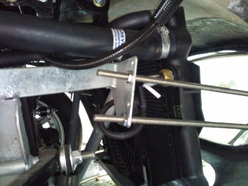
The rear nudge bars are fairly simple with L shaped brackets to attach to the boot floor:

The studding feeds through the body and attaches to 2 out of the 4 holes in the chassis:
The rear nudge bars are fairly simple with L shaped brackets to attach to the boot floor:
Exhausts
Back last summer I managed to get some 2nd hand exhausts which were in good condition and perfect for my headers. The questions was what to do with the steel headers to stop them rusting. I looked into ceramic coating, but it's rather expensive, and doesn't help reduce the under-bonnet heat, so I opted for exhaust wrap. The problem with wrap is that it can absorb moisture when the car is left and that will rust the pipes. So, a coating of very high exhaust paint (actually I used fireplace paint!) solved the rusting problem and the exhaust wrap will reduce the heat. All good after a very wet winter with only a few engine starts... The wet winter has caused a clutch problem though - more on this later :-(


Once the headers were wrapped and fit, cutting holes in the body was simple and looked great once the plated were attached:
Once the exhaust L section was clamped on to the headers, adding the side pipes was easy with a couple of bolt holes into the chassis and some new rubber bobbins. I have also some exhaust filler to keep the noise down for IVA, but I'll stuff that into the exhaust just before the test so it has maximum effect.
I couldn't wait to fire up the v8 beast now that the exhaust was attached. Sadly it coughed and spluttered and there was finally a bang and burst of flame from the air filter. I quickly turned it off and waited for my pulse to return to normal. After some thinking and forum advice, I checked the timing, since there was fuel, and clearly spark. It was way out! I set it to 10deg BTDC and boom! It fired up and made a great noise. After a little while it even ticked over fairly well. I then got a boast of confidence and felt like I could rule the world. So I slid it into gear and reversed slowly a few feet.....YES! It moved. Sadly after a few feet the clutch pedal went to the floor and the car jerked backwards and thankfully stalled. The clutch stopped working. if you read on, this became the bane of my life for the next 8 months :-(
Sunday, 18 May 2014
The boot lid fixings
The boot lid fixings included the hinges, the lock, the support stay and the number plate light.
The hinges were fairly straightforward once they were lined up

The boot lock and handle.


And lastly the number plate light. Easy to fit with 2 bolts, but the tough part is the wiring. I didn't want to attach a wire along the inside of the boot and knew it was possible to feed a wire between the inner and outer skins of the boot. With a hole drilled near the light and another near the hinge, I followed the advice on the forums to get the wire through. The idea is to have a piece of thread tied to a metal nut and feed to nut through the channel using a magnet. Sounds easy, but mine kept getting caught on rough inside of the fibreglass. I solved it by using a piece of net curtain wire, strong enough to push through the hole and flexible enough to feed around the corners. Once through the channel and out the other side it was a simple matter to tie the piece of wire to it and pull it through. Adding a a grommet in each hole and job done!


The hinges were fairly straightforward once they were lined up
The boot lock and handle.
And lastly the number plate light. Easy to fit with 2 bolts, but the tough part is the wiring. I didn't want to attach a wire along the inside of the boot and knew it was possible to feed a wire between the inner and outer skins of the boot. With a hole drilled near the light and another near the hinge, I followed the advice on the forums to get the wire through. The idea is to have a piece of thread tied to a metal nut and feed to nut through the channel using a magnet. Sounds easy, but mine kept getting caught on rough inside of the fibreglass. I solved it by using a piece of net curtain wire, strong enough to push through the hole and flexible enough to feed around the corners. Once through the channel and out the other side it was a simple matter to tie the piece of wire to it and pull it through. Adding a a grommet in each hole and job done!
Roll bar
The roll bar was easy to fit using the manual as a guide, and ensuring the correct height was achieved. Cutting the holes in the body needed to be fairly accurate. To mark the holes from the underside I used an empty sealant tube as a guide from the chassis up towards the body. Once the hole was cut and enlarged slightly the roll bar slid neatly into place. I did notice that the legs were quite parallel, and as it slid down I needed to widen the holes on one side - it didn't matter as the escutcheon plate hid all that. It was a tight fit and I greased the chassis and used a rubber mallet to tap it home. The bar is stainless steel and therefore VERY hard to drill. Once mounted I slowly drilled a hole through the bar and chassis using new titanium tipped drill bits.

Saturday, 17 May 2014
Seat Belt Strenghening
On the MkIII Sumo Pilgrim the seat belt reels and upper support are attached to the fibreglass body. To strengthen and support the seat belts, metal panels are bonded into the body. The seat belts have passed a strength test which has been filed with VOSA and I will be referring to that in my IVA. However, some have failed on not having sufficient support for the seat belt mounting. So, to be on the safe side I have added supports and attached the existing metal to the chassis:
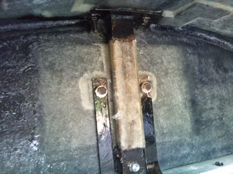


From inside the boot, the supports can be seen with the bonded metal plates. I've added the additional vertical supports either side of the main support bar and bolted them to the chassis. I've taken photos at every stage to show Mr. IVA that the seat belts are bonded to the metal (and not the fibreglass body), and these in turn are attached to the chasssis. Safe? I think so! From above:
And finally both seat belts attached and secure:
Bonnet fittings
It's been a while since I posted (over a year - whoops!)... So back in Feb 2013 I started to work on adding all the fun stuff to the bonnet: Handles, Stay, Grill:
Adding the handles was very simple, but as with all body drilling there was lots of checking and double checking before drilling the first hole. Here the bonnet off the car showing the handle:
 and the underside of the grill. I used a piece of rubber U-tube to hold the grill and then bonded it to the underside of the bonnet


Now the bonnet has handles and opens and closes its time to fit the stay. I looked into getting a couple of gas struts to support the bonnet, but since they aren't cheap and how often do you really need to open the bonnet... I have added it to my upgrade list. They do look good though - see a video of a cobra with bonnet struts:
https://www.youtube.com/watch?v=ma0FWMy6FXc
Once I figured out the measurements of where to place the bonnet stay it was a simple job to fit - I did have to make a small bracket to make fitting to the body stronger and slight lower:

Adding the handles was very simple, but as with all body drilling there was lots of checking and double checking before drilling the first hole. Here the bonnet off the car showing the handle:
Now the bonnet has handles and opens and closes its time to fit the stay. I looked into getting a couple of gas struts to support the bonnet, but since they aren't cheap and how often do you really need to open the bonnet... I have added it to my upgrade list. They do look good though - see a video of a cobra with bonnet struts:
https://www.youtube.com/watch?v=ma0FWMy6FXc
Once I figured out the measurements of where to place the bonnet stay it was a simple job to fit - I did have to make a small bracket to make fitting to the body stronger and slight lower:
Subscribe to:
Posts (Atom)