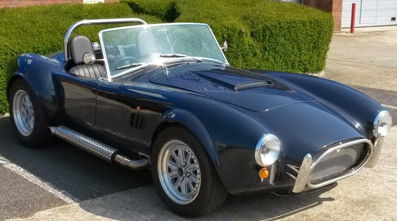
Pages

Monday 16 June 2014

Dashboard dials

I ordered the dashboard dials and sensors from ETB Instrument. I can really recommend them. Great product, arrived on time and packaged brilliantly! I used them on my previous kit car and had no trouble at all.

There latest speedo and rev counters come with built in warning lights (sadly not shown on their website). Not having the extra LEDs makes the dash a lot more tidy. The speedo has handbrake, charge and oil pressure warning lights and the rev counter has the other 3 (left/right indicator and hi-beam)


I've made a temporary dash to help sort the wiring out before I fit the full dash - much easier to take in and out.
Starting to draw up a wiring diagram for it and buy some multi-connector plugs to make it easy to disconnect all the dials - it'll also help with keeping the wiring neat and tidy for Mr. IVA man, as under-dash wiring can get into a real mess :-)

Sunday 25 May 2014

Alternator Charge Light

Back when I first started the engine I checked the oil pressure light and charge lights were going out once the engine was started. The oil pressure light went out showing I had oil pressure and the wiring was correct. Sadly the charge warning light connected to the alternator stayed lit. So stuck it on my ToDo list and got on with more fun stuff like getting the clutch fixed :-)

So why is the charge light staying on when the engine is running. Alternator is new, but could be faulty or my wiring. Turned out to be neither.

I understand that one side of the light has 12v and it is then earthed through the alternator spade connector. When the engine is running and the alternator is working that same spade connector switches to 12v and therefore the light is no longer earthed and goes out. However, what I didn't know is that the 12v supplied to the alternator also provides an initial magnetic charge to energize rotating field coil.

Back when I was testing the oil pressure light and alternator charge light the engine wasn't running too well. So I focused on getting the engine started and then connected up the test light to see if a) the oil pressure light was out - check! and b) charge light was out. But of course it didn't go out because I connected my test light AFTER the engine was started. Doh!! So I wired it all up this morning, ignition on, light on, engine started, light off - simple.

Saturday 24 May 2014

Doors

From all the posts and chat on the forums it appears that getting the doors lined up and fitting is a complete nightmare. After painting the hinges and cutting holes in body, I trial fitted them and it appeared there was a lot of movement, up/down, left/right. So I set them in the middle to allow movement either way. As per the instructions I offset them from the chassis with an m10 nut.

I held the doors up against the hinges and used bits of folded cardboard to pad the door away from the body. After marking some holes in the door it was obvious that I was going to need a different number of washers between the hinge and the door. I tighten it all up and was pleasantly surprised that the door didn't look too bad. It open and closed :-) It did rub slightly on the edge near the hinge, but a little filing sorted that. By adding/removing washers to one of the 4 holes bolting the door to the hinge I was able to get pretty good alignment. Add to that moving the body in a little and bolting to the chassis the doors fit fairly well. The secret is to secure the hinge to the chassis and not be tempted to adjust that, and only adjust the hinge to door bolts - well it worked for me. I probably only spent 1/2 a day aligning each door.

Next came to the door latches. I didn't keep the original Sierra door latches so I bought some from Car Builder solutions and some flush door handles.


I had to make up some brackets as the ones supplied by Pilgrim were intended for the bigger Sierra handles (which I think look rubbish. These chrome handles look much better. Once the bracket was installed I made up some door cards from 3mm marine ply. I connected the door handles to the latched using a piece of bend wire from an old wire coat hanger!

Since the door cards go on last and clip on the handles needed to be secured to the door before the card goes on and then lastly the plastic surround.


Next is to cover the cards in vinyl (or leather) and decide whether I need/want a pocket in the door.


Thursday 22 May 2014

The woes of my clutch

Fixed Once...
The first time the clutch broke I discovered that the push rod which connects the slave cylinder to the clutch arm had fallen off. I can only assume that it wasn't properly connected. I reattached it and couldn't get the clutch to disengage. I bled the clutch and still couldn't get it to disenage. This was starting to get annoying as I knew it worked before. After a 2nd bleed of the clutch including purging the slave cylinder, I tried a slightly longer push rod (well, a piece of m8 studding ;-) It still didn't work. To test it I had my son in the car pressing the pedal to the floor with the rear wheel jacked up. The wheel should have turned while in gear if the clutch was disengaging. I gave it one last try and pushed the wheel round hard and it suddenly moved. The clutch plate must have been stuck to the flywheel. Hooray, it was fixed. I should have heard the alarm bells at this point, if it was starting to sieze with the damp weather we were having it wasn't going to "go away". I simply patted myself on the back, ticked off the "get clutch working" job and moved onto fitting the doors.

It gets worse!
I needed to move the car out of the car port to fit the other door (car port isn't wide enough for both doors to be open). So, I fired up the beast and tried to engage reverse. Why wasn't it going into reverse? Oh No!!! The clutch had broken again. But, but, but, nothing had changed. It was working, how could it have stopped working. I checked the push rod, I bled the clutch (3 times!!), I jacked it up and could see the push rod moving the release arm. The stupid clutch plate was seized again.

The forum advice to free a seized plate was to get the engine to running temperature and blip the throttle. Made some good noise, but no joy. Failing that start it in gear and apply the brake. The car shot backwards out of the car port and applying the brakes just stalled the engine. Other advice included driving in gear and accelerating hard - not possible with a 1/2 finished non-road legal car. So it meant taking the gearbox out. No........!!!!!

After many weeks of pondering and looking at the problem of how to remove the gearbox while the engine is in the car and doing it all on my back I kept finding other simpler job to do. It was starting to frustrate me and I was spending every waking minute worrying about how it could be done. I finally got down to the business of removing the gearbox to get to the clutch.

First I jacked up the car as high as I could to give me lots of room underneath. I then made a simple little trolley to sit under the gearbox and allow me to slide it backwards away from the engine. Getting the gearbox and engine apart was no problem. I removed the clutch cover and found the clutch plate was nicely stuck to the cover. I had to use a mallet to get it off. I didn't mess around cleaning it, I just bought a new one. Not cheap, but worth it!!

The the fun and games started. 
After aligning the clutch plate and attaching to the flywheel my back and forearms were starting to ache. I tried and tried, but I couldn't get the bell-housing to re-mate with the engine - wiggling, pulling, lifting, pushing and swearing had no effect. I even strained a muscle in my chest doing it. The clutch plate was obviously not aligned enough to allow the gearbox to connect. I bought a better clutch aligning tool that aligns the plate to the flywheel rather than the crappy plastic one that aligns plate to cover. And hey presto, with some wiggling and pushing I managed to get the bell-housing close enough to fit the bolts.

With it all bolted up I cheered loudly when the clutch disengaged!! Made my day!!

Rear Lights

The rear needs to include:
 - Tail lights
 - Brake lights
 - Indicators
 - Reversing light
 - Fog light
 - and last but not least reflectors

After much thought I went for a combined red tail and brake light and an indicator on each side which fit nicely in the space on the body. Reflectors didn't seem to fit anywhere sensible, so I made up a simple bracket to fit to the nudge bar supports:


And it sits nicely in the gap in the nudge bar:

The single fog and reversing light (which are both IVA requirements) again didn't fit anywhere on the body. So after much searching I found a matching pair of slim box lights, one white, and one red. Using two large P clips with rubber covering I bolted these to the nudge bar:

Monday 19 May 2014

Nudge bars

Fitting the nudge bars back and front was fun and instantly rewarding as they look great. The front wasn't as easy as I thought, as even with the holes in body drilled out the supports didn't fit. Advice from Pilgrim was to add a small bend to the studding that supports the nudge bar.
The studding feeds through the body and attaches to 2 out of the 4 holes in the chassis:


 The rear nudge bars are fairly simple with L shaped brackets to attach to the boot floor:


Exhausts

Back last summer I managed to get some 2nd hand exhausts which were in good condition and perfect for my headers. The questions was what to do with the steel headers to stop them rusting. I looked into ceramic coating, but it's rather expensive, and doesn't help reduce the under-bonnet heat, so I opted for exhaust wrap. The problem with wrap is that it can absorb moisture when the car is left and that will rust the pipes. So, a coating of very high exhaust paint (actually I used fireplace paint!) solved the rusting problem and the exhaust wrap will reduce the heat. All good after a very wet winter with only a few engine starts... The wet winter has caused a clutch problem though - more on this later :-(

Once the headers were wrapped and fit, cutting holes in the body was simple and looked great once the plated were attached:
Once the exhaust L section was clamped on to the headers, adding the side pipes was easy with a couple of bolt holes into the chassis and some new rubber bobbins. I have also some exhaust filler to keep the noise down for IVA, but I'll stuff that into the exhaust just before the test so it has maximum effect.


I couldn't wait to fire up the v8 beast now that the exhaust was attached. Sadly it coughed and spluttered and there was finally a bang and burst of flame from the air filter. I quickly turned it off and waited for my pulse to return to normal. After some thinking and forum advice, I checked the timing, since there was fuel, and clearly spark. It was way out! I set it to 10deg BTDC and boom! It fired up and made a great noise. After a little while it even ticked over fairly well. I then got a boast of confidence and felt like I could rule the world. So I slid it into gear and reversed slowly a few feet.....YES! It moved. Sadly after a few feet the clutch pedal went to the floor and the car jerked backwards and thankfully stalled. The clutch stopped working. if you read on, this became the bane of my life for the next 8 months :-(


Sunday 18 May 2014

The boot lid fixings

The boot lid fixings included the hinges, the lock, the support stay and the number plate light.
The hinges were fairly straightforward once they were lined up

The boot lock and handle.


And lastly the number plate light. Easy to fit with 2 bolts, but the tough part is the wiring. I didn't want to attach a wire along the inside of the boot and knew it was possible to feed a wire between the inner and outer skins of the boot. With a hole drilled near the light and another near the hinge, I followed the advice on the forums to get the wire through. The idea is to have a piece of thread tied to a metal nut and feed to nut through the channel using a magnet. Sounds easy, but mine kept getting caught on rough inside of the fibreglass. I solved it by using a piece of net curtain wire, strong enough to push through the hole and flexible enough to feed around the corners. Once through the channel and out the other side it was a simple matter to tie the piece of wire to it and pull it through. Adding a a grommet in each hole and job done!


Roll bar

The roll bar was easy to fit using the manual as a guide, and ensuring the correct height was achieved. Cutting the holes in the body needed to be fairly accurate. To mark the holes from the underside I used an empty sealant tube as a guide from the chassis up towards the body. Once the hole was cut and enlarged slightly the roll bar slid neatly into place. I did notice that the legs were quite parallel, and as it slid down I needed to widen the holes on one side - it didn't matter as the escutcheon plate hid all that. It was a tight fit and I greased the chassis and used a rubber mallet to tap it home. The bar is stainless steel and therefore VERY hard to drill. Once mounted I slowly drilled a hole through the bar and chassis using new titanium tipped drill bits.

Saturday 17 May 2014

Seat Belt Strenghening

On the MkIII Sumo Pilgrim the seat belt reels and upper support are attached to the fibreglass body. To strengthen and support the seat belts, metal panels are bonded into the body. The seat belts have passed a strength test which has been filed with VOSA and I will be referring to that in my IVA. However, some have failed on not having sufficient support for the seat belt mounting. So, to be on the safe side I have added supports and attached the existing metal to the chassis:

From inside the boot, the supports can be seen with the bonded metal plates. I've added the additional vertical supports either side of the main support bar and bolted them to the chassis. I've taken photos at every stage to show Mr. IVA  that the seat belts are bonded to the metal (and not the fibreglass body), and these in turn are attached to the chasssis. Safe? I think so! From above:
And finally both seat belts attached and secure:


Bonnet fittings

It's been a while since I posted (over a year - whoops!)... So back in Feb 2013 I started to work on adding all the fun stuff to the bonnet: Handles, Stay, Grill:

Adding the handles was very simple, but as with all body drilling there was lots of checking and double checking before drilling the first hole. Here the bonnet off the car showing the handle:
 and the underside of the grill. I used a piece of rubber U-tube to hold the grill and then bonded it to the underside of the bonnet


Now the bonnet has handles and opens and closes its time to fit the stay. I looked into getting a couple of gas struts to support the bonnet, but since they aren't cheap and how often do you really need to open the bonnet... I have added it to my upgrade list. They do look good though - see a video of a cobra with bonnet struts:
https://www.youtube.com/watch?v=ma0FWMy6FXc

Once I figured out the measurements of where to place the bonnet stay it was a simple job to fit - I did have to make a small bracket to make fitting to the body stronger and slight lower: